Author: Jason Julius

Web-400pixels-techtip_23.jpg

Repair Solutions for Common Fiberglass Damage

Maintenance of insulated booms on aerial devices and digger derricks is critical to preserving the integrity of the insulating qualities of the machines. While insulated equipment is required to be dielectrically tested each year, daily and periodic inspections of fiberglass components should be performed as directed by the manufacturer.

There are two common types of damage and wear that may affect the integrity of a fiberglass boom. The first, structural damage, is classified according to the type of damage – cuts, bruises or overloads. The second type is wear that occurs where there is contact with other components, such as at boom rests or at fiberglass-to-steel joints.

In both cases, the damage must be assessed to see if it is repairable. Each manufacturer provides information specific to the type and shape of its boom designs. For example, Terex Utilities provides two charts for the equipment it manufactures, which break the damage into minor damage and major damage. The severity of the damage will determine the course of action. Major damage must be reported to the manufacturer for analysis to determine if it can be repaired. Examples include overload damage, complete penetration of the wall or major damage within 24 inches of previously repaired major damage.

Before measuring the depth of a cut or gouge, or the diameter of a bruise, be sure to identify the location of the damage. Location is important because some areas of the boom must support greater amounts of weight than others, which affects whether the damage is considered minor or major.

Location is identified at a point along the length of the upper boom and by cross-section. Terex booms are divided into 10 equal lengths from the boom tip (Section 1) to the base (Section 10), and the cross-section is divided into four quadrants. There is one quadrant map for square and rectangular booms, and another quadrant map for round booms. Lower-boom insulating sections are considered as Section 10 because of the short length and loading situation.

An Example of Structural Damage

Web techtip 23

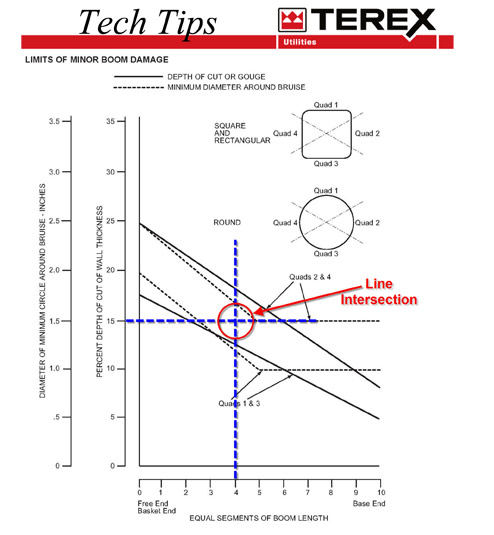
If the intersecting point is below the solid line for Quadrant 1, the boom is repairable. In this example, the intersecting point falls above the solid line for Quadrant 1, indicating the Major Damage Chart must be used.

A fiberglass boom with a cut on the top would be in Quadrant 1. When measuring the damage, it is determined that the cut is 15% of the thickness of the boom. Note that this measurement does not include the thickness of the finish, which does not add to the structural strength of the boom. Then, divide the boom length into 10 equal parts. In this example, the damage is in Section 4.

Draw intersecting lines from 15% and Section 4 on the Minor Boom Damage Chart. If the intersecting line is below the solid line for Quadrant 1, the boom is repairable. In this example, the intersecting point is above the solid line for Quadrant 1, indicating the Major Damage Chart must be used.

Bruises are evaluated by removing the finish and measuring the diameter of a circle that completely covers the bruise area. Use the scale for bruises to draw the intersecting lines to determine the extent of the damage in a similar way to the previous example.

Common Wear Points
Two common fiberglass wear points are at the boom rest and at fiberglass-to-steel joints. Maintain boom rests by replacing rubber or plastic components as needed. Regularly clean boom rests to remove embedded dirt or gravel.

Improperly maintained joints can lead to corrosion of the steel boom section or allow water or other contaminants to wick into the fiberglass. Rust or dirt that gets inside of a boom can cause dielectric failure. In addition, when moisture penetrates fiberglass windings, the dielectric strength of the fiberglass can be reduced.

To properly seal fiberglass-to-steel joints, first remove the sealant past the point where it has been compromised to allow for thorough inspection. Clean the steel to remove any rust. Naval Jelly and Evapo-Rust are two commercially available products that are suggested for this task. Do not use a rust converter product. Sandblasting may be necessary if minor pitting exists; however, if pitting is extensive, contact the manufacturer to determine if it is safe to repair the boom or if the boom must be replaced.

After priming and painting the area, apply caulking at the joint, ensuring that it adheres to both surfaces. Once you’ve addressed the issues causing wear or damage to the fiberglass, then take proper steps to repair the fiberglass. 

Gel Coat Repairs
Damage to the boom’s outer gel coat can also cause dielectric failure. Before making gel coat repairs, refer to the Minor Boom Damage and Major Damage charts to determine if the boom is repairable. Damage to the gel coat should be less than 1 inch in diameter.

Acceptable materials for repairing fiberglass boom surfaces include polyester fiberglass resin; E-Glass fiberglass mat and cloth; white neopentyl glycol gel coat with wax; silicone spray; and hot stick wax. Verify the gel coat to be used does not contain conductive components.

Clean the boom surface by washing it with a product that is not abrasive and does not leave a residue. Rinse, dry and sand the damaged area, then resurface it with the same product. Allow the area to dry. Once dry, spray a thin layer of silicone material or hot stick wax and wipe with a lint-free cloth to remove excess. 

Boom Refinishing
If the damaged area is larger than 1 inch in diameter or the boom needs to be refinished, start by cleaning the surface with something that is not abrasive and does not leave a residue. Remove the caulk seals of the fiberglass-to-steel joints if there is any visible rust.

Allow the boom to dry for 24 hours in an environment with less than 25% relative humidity. The recommended temperature is between 100 to 140 degrees Fahrenheit.

Thoroughly sand the outside surface less than 0.015 inches (0.38 millimeters). Once sanded, only handle the boom using clean gloves. Oil and salt from bare hands can contaminate the surface. Additionally, do not expose the sanded boom to humidity over 40%. At this point in the process, it is important to move as quickly as possible from unfinished to refinished. If the reason for refinishing the boom is because it failed a dielectric test, you may want to retest after removing the gel coat to determine if that solved the problem. Part of the initial inspection should have included a visual inspection of the interior for oil leaks, conductive hoses or indications of flashover.

Resurface the boom, referring to manufacturer instructions for minimum and maximum thickness range as well as how thick of a coat is permitted in one application. Air-dry the boom at 77 degrees Fahrenheit for 12 to 24 hours, then caulk fiberglass-to-steel joints. A gel coat with a wax layer or the addition of hot stick wax or a silicone layer is recommended to encourage water to bead on the surface.

The final step after reassembly is to complete an operational test from lower and upper controls. Successful completion of a periodic dielectric test per ANSI A92.2 is also required. Before placing the unit back in service, repair any other issues that caused the damage to prevent future damage.

Remember that regular inspections are critical to maintaining the integrity of your insulated machine. Understanding the types of damage and proper repairs will help mitigate the issues found. Regardless, throughout the process, the manufacturer should be consulted for best results.

About the Author: Jason Julius oversees technical support and training at Terex Utilities. Information for this article came from the company’s Tech Tips #23, #129 and #149. These and other technical support documents are available via the Technical Support tab at www.terex.com/utilities.

Web-Monday-Part-1-076_rev.jpg

Pole Removal and Setting Techniques to Prevent Digger Derrick Damage

Digger derricks are among the most versatile tools on a utility line construction project. They are built to tackle a myriad of tasks, from digging holes and lifting and setting poles to turning in screw anchors, putting lineworkers in the air and setting transformers. In short, digger derricks are hardworking tools used to solve a variety of challenges.

However, given the versatility of a digger derrick, there are specific work practices that need to be followed, such as those for removing and setting poles. When work practices are not performed correctly, equipment can be damaged. If you’ve ever used a digger derrick boom to rock a pole loose or used the load line to forcibly remove a pole, you should know both practices are prohibited by manufacturers. They are prohibited because doing so can impose unknown loads and forces on the digger derrick that its key components are not designed to withstand.

Among the main components of a digger derrick that can sustain damage due to pole rocking are the pedestal, turntable, boom, cylinders, pole guides, subframe, outriggers and winch. All of these are costly to repair or replace if damaged, plus downtime for repairs can put the equipment out of service for extended periods.

Attempting to lift a pole that is frozen to, embedded in or fastened to the ground could shock load and cause an overload to the digger derrick components. So, instead of using the boom’s brute force, use a pole puller, which can provide much greater force to loosen the pole. In extreme cases, it may be necessary to dig one or more holes with the digger derrick auger alongside the pole to loosen the soil, assisting the pole puller. Once the pole is loose, the lift cylinders can then carefully lift the freely suspended pole while using pole guides to maintain control. The act of lifting should only be done based on the lift cylinder capacity, the load chart parameters and the number of parts of line. Do not use the pole guides to lift the pole; they should only be used to help control the pole as it is being lifted. Additionally, the rigging that attaches the pole to the load line must be below the balance point of the pole to keep the butt end heavy and down.

Once it has been lifted, it is critical to maintain control of the pole at all times. Shifting loads or losing control of the pole can cause failure of the pole guides, load line or rigging, resulting in unpredictable pole movement. Losing control can lead to serious injury or death as well as shock-loading, side-loading, and component damage or failure.

Know Your Load Weight
It also is critical to know the weight of the free-hanging pole before selecting a digger derrick for the task. If the load weight is unknown, charts are available to provide an approximate weight based on the material the pole is constructed from and the pole’s length. When determining weight, take into consideration anything that may be attached to the pole, such as crossmembers, transformers, insulators or wire. Consult the unit-specific load charts on the digger derrick to make sure it has the capacity needed to lift the load through the complete path that the load will travel, beginning with the extraction point and ending with the location of the final placement. You can avoid shock-loading the boom by maintaining control of the load at all times and only lifting loads that are not embedded in the ground.

Setting a pole, in most cases, provides fewer opportunities for equipment damage. The load line must be above the balance point of the pole and all components on the pole. Never use pole guides as support. They are meant to guide the pole, helping to keep it under control, and reduce the chances of causing side-loading or shock-loading to the boom as well as damage to the pole guides themselves. 

Alternate Equipment and Inspections
In some scenarios, alternate equipment might be necessary to dig a hole. The type of equipment used should be dictated by the ground conditions that need to be augered. For example, in hard rock areas, a core barrel can be used instead of a standard auger to increase productivity. Areas of shale require different types of tooling than sandy or clay soil conditions. In addition to switching tooling, a pressure digger – rather than a digger derrick – may be required to dig in areas of hard rock. Knowing which tools to use and having those tools available can save an operator countless hours, reduce wear and tear on equipment, and extend the life of the auger and teeth.

Finally, when inspecting a digger derrick, there are a few telltale signs that booms have been used improperly. Look for cracks, rust, loose paint, loose fasteners, deformation and other damage to the boom, pedestal and subframe. This may be evidence of shock-loading or overloading from using the boom to rock a pole or pulling a pole with a load line that was not freely suspended. Bent pole guides can be a sign that they are being used improperly to support the pole rather than guide it. Damage to the load line can be an indication of misuse from using the load line as a sling.

About the Author: Jason Julius works in technical support and training development for Terex Utilities (www.terex.com/utilities). He is a digger derrick practical examiner for the digger derrick operator certification through NCCCO. Julius also served on a task force to develop NCCCO foundation drill rig certification.

*****

Setting Up a Pole Puller
A hydraulic pole puller is equipped with a heavy-duty steel base and slotted head for attaching a chain loop. To set it up, begin by placing the pole puller on the side of the pole vertically – either toward or away from the digger derrick boom – so the force exerted does not result in a side pull on the boom.

Next, drop the eye of the pulling chain over the slotted head of the pole-puller ram, loop the chain snugly around the pole and insert the chain end in the slot on the pole-puller ram. Make sure the chain is not kinked or twisted. Do not hook the chain and pole puller together using the chain as a choker chain around the pole. Both ends of the chain must be attached to the pole-puller ram to prevent overload of the chain and possible serious injury or death if the chain fails.

Attach auxiliary hoses from the digger derrick to the tool couplers on the pole puller. Use a section of nonconductive hose between the pole puller and the truck. Make sure there is no pressure in the lines before attempting to attach the hoses. The truck may need to be turned off to release pressure and allow the lines to be connected. Pull on each hose to make sure they are fully engaged with the tool couplers to prevent damage to the pole-puller fittings.

Wrap an appropriately rated sling around the pole above the pole’s center of gravity, attach the load-line hook to the sling and snug up the load line. Activate the pole puller by slowly operating the control valve to slowly lift the pole. Pole pullers can develop 40,000 to 60,000 pounds of force, so stand clear to avoid personal injury.

After each pull is made, winch up the load line to keep the line snug and reposition the boom as necessary to maintain control of the pole. Reposition the chain around the pole as needed to account for the pole’s tapering.

To prevent damage to the pole-puller cylinder rod when retracting, maintain the pole puller in an upright position.

Finally, use the pole guides and the load line to keep the pole vertical until it is freely suspended. Once the pole is suspended, use the load line and lift cylinders to remove it from the hole and place it in the desired location.

Utility Fleet Professional

360 Memorial Drive, Suite 10, Crystal Lake, IL 60014 | 815.459.1796

KNOWLEDGE, INSIGHT & STRATEGY FOR UTILITY FLEET LEADERS

Utility Fleet Professional is produced by Utility Business Media, Inc.   View Capabilities Statement

Get the Utility Fleet Professional Digital Edition App

Get the iP Digital Edition App


© All rights reserved.
Back to Top